In the world of industrial automation and process control, instrumentation serves as the “nervous system” of a plant. However, even the most advanced sensors and controllers are only as effective as the paperwork supporting them. A fragmented documentation process leads to costly delays, safety hazards, and massive headaches during the final stages of a project.
To ensure a project stays on track, engineers must follow a rigorous instrumentation documentation workflow. This journey begins at the conceptual stage and concludes only when the system is fully operational. In this guide, we explore the lifecycle of documentation from FEED through to SAT, ensuring a smooth transition into commissioning.
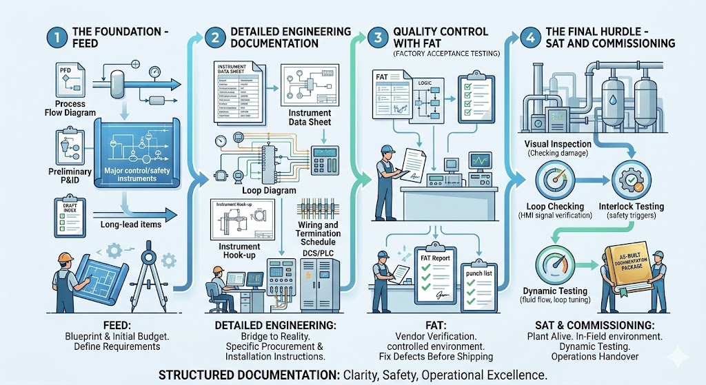
Phase 1: The Foundation – FEED (Front-End Engineering Design)
The FEED phase is where the project’s technical requirements are defined and the initial budget is established. From a documentation standpoint, this is the “blueprint” phase.
During FEED, the focus is on high-level design. Key documents produced include:
Process Flow Diagrams (PFDs): Highlining the main process stream.
Preliminary Piping and Instrumentation Diagrams (P&IDs): Identifying the major instruments required for control and safety.
Preliminary Instrument Index: A draft list of every instrument expected in the plant.
The goal of FEED is to identify long-lead items and technical challenges before the heavy lifting of the project begins. Mistakes made here ripple through the entire workflow, making accuracy paramount.
Phase 2: Detailed Engineering Documentation
Once the FEED is approved, the project moves into the most labor-intensive stage. Detailed engineering documentation is the bridge between a conceptual design and a physical reality. This phase provides the specific instructions needed for procurement, installation, and wiring.
Critical documents in this phase include:
Instrument Data Sheets: These specify the exact technical parameters of every device—range, material, output signal, and environmental ratings.
Loop Diagrams: Detailed drawings showing the signal path from the field instrument to the control system (DCS/PLC).
Instrument Hook-up Drawings: Instructions on how the instrument should be physically mounted and connected to the process piping.
Wiring and Termination Schedules: Essential for the electricians who will land thousands of wires in junction boxes and control panels.
Without comprehensive detailed engineering documentation, the construction team is essentially working blind, leading to “field fixes” that compromise the integrity of the design.
Phase 3: Quality Control with FAT (Factory Acceptance Testing)
Before any equipment arrives at the job site, it must pass the FAT (Factory Acceptance Test). This is a critical milestone where the vendor demonstrates that the system meets the functional requirements specified in the engineering phase.
During FAT, the documentation workflow shifts from “creation” to “verification.” Engineers use the data sheets and logic diagrams created during detailed engineering to test the hardware and software in a controlled environment.
The FAT Report: This document records every test performed, any failures encountered, and the subsequent “punch list” of items the vendor must fix before shipping.
A successful FAT significantly reduces the risk of discovering major software bugs or hardware defects once the equipment is already installed in the field.
Phase 4: The Final Hurdle – SAT and Commissioning
Once the equipment is installed on-site, the focus shifts to SAT (Site Acceptance Testing). While FAT tests the system in the factory, SAT tests it in its final environment, integrated with the actual field wiring and process equipment.
The Role of SAT
The SAT documentation confirms that the equipment survived transit and was installed correctly. It involves:
Visual Inspections: Checking for physical damage and correct mounting.
Loop Checking: Verifying that a signal from a field transmitter correctly reaches the HMI (Human-Machine Interface).
Interlock Testing: Ensuring safety systems trigger correctly under simulated fault conditions.
Transitioning to Commissioning
Commissioning is the final stage of the instrumentation workflow. This is where the plant is brought to life. The documentation from previous stages—the instrument index, the loop drawings, and the SAT reports—serves as the “as-built” record.
During commissioning, the focus is on dynamic testing: introducing actual process fluids, tuning control loops, and verifying that the plant operates safely and efficiently at scale. The final deliverable is a complete “As-Built” documentation package, which is handed over to the operations and maintenance teams.
Conclusion: Documentation as a Roadmap to Success
The journey from FEED to SAT is complex, but a structured approach to detailed engineering documentation ensures that nothing is left to chance. By maintaining a rigorous workflow, project managers can avoid the pitfalls of disorganized data, ensuring that commissioning is a celebration of a job well done rather than a scramble to fix errors.
In industrial engineering, the paper trail is just as important as the hardware. When your documentation is solid, your project is built on a foundation of clarity, safety, and operational excellence.