In the world of functional safety, clarity is the ultimate safeguard. When designing Safety Instrumented Systems (SIS), the transition from a Hazard and Operability Study (HAZOP) to actual logic implementation can be fraught with errors. This is where the Cause & Effect matrix becomes an indispensable tool.
For engineers working within the framework of IEC 61511, a well-structured matrix isn’t just a drawing; it is a fundamental part of the Safety Requirements Specification (SRS). In this guide, we will explore the good practices for Cause & Effect development & review to ensure your facility remains safe and compliant.
Why a Robust Cause & Effect Matrix is Vital for Process Safety
A Cause & Effect (C&E) matrix provides a clear, tabular representation of the logic that links sensing elements (Causes) to final elements like valves or motors (Effects). Under IEC 61511, the functional safety lifecycle demands that logic is not only functional but also verifiable and maintainable.
Without a structured C&E, the risk of “logic creep” increases—where the intended safety function is lost in a sea of complex programming. By prioritizing a clean structure, you enhance process safety by making the safety logic understandable for operators, maintenance technicians, and functional safety auditors alike.
Key Components of a Compliant Cause & Effect Matrix
To achieve IEC 61511 compliance, your matrix must be more than a simple grid. It needs to contain specific metadata and functional details.
1. Identifying the Causes (Inputs)
The “Cause” side of the matrix should clearly list the input devices. Good practices dictate that you include:
- Tag Numbers: Precise identification of the instrument (e.g., PT-101).
- Trip Setpoints: The exact process value that triggers the safety action.
- Voting Logic: Specification of 1oo1, 1oo2, or 2oo3 configurations.
- Description: A brief explanation of the hazard being mitigated (e.g., “High Pressure in Vessel A”).
2. Defining the Effects (Outputs)
The “Effect” side details what happens when a trip occurs. This should include:
- Final Element Tags: (e.g., XV-101 or Pump P-201).
- Fail-Safe State: Clearly state whether the valve should Close (FC), Open (FO), or the motor should De-energize.
- Timing Requirements: Any necessary delays or sequencing requirements.
3. The Logic Intersection
The intersection points (often marked with an “X”) define the relationship. For complex systems, different symbols may be used to represent “Energize to Trip” vs. “De-energize to Trip” logic, provided a clear legend is included.
Good Practices for Cause & Effect Development & Review
The Cause & Effect development & review process is where most errors are caught—or unfortunately, where they are sometimes introduced. Following these industry-standard good practices will minimize risk:
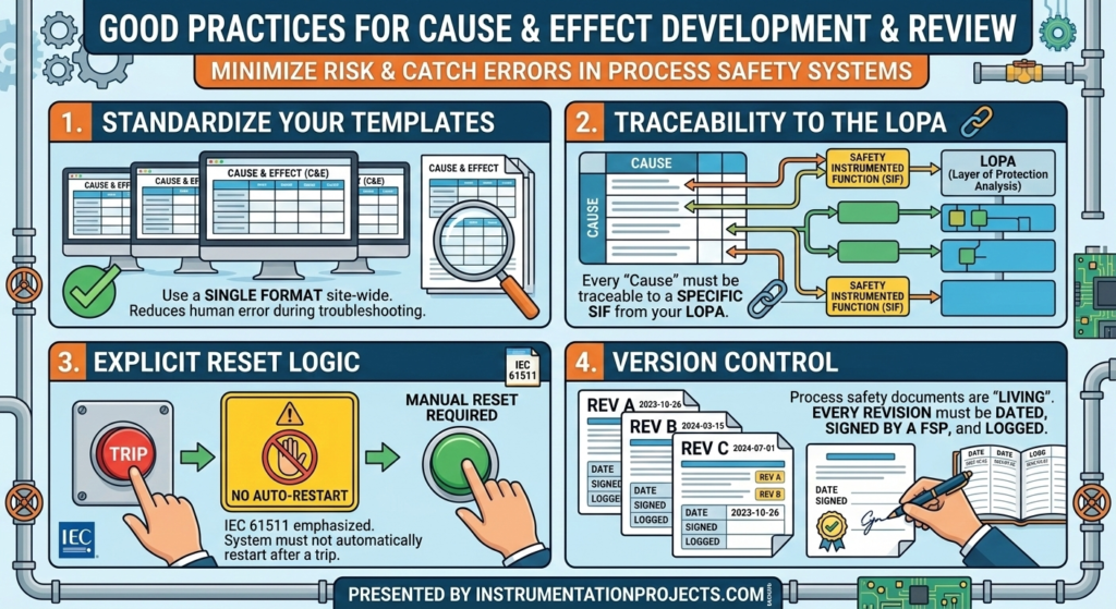
- Standardize Your Templates: Ensure that every C&E matrix across your site follows the same format. This reduces human error during high-stress troubleshooting.
- Traceability to the LOPA: Every “Cause” in your matrix should be traceable back to a specific Safety Instrumented Function (SIF) identified in your Layer of Protection Analysis (LOPA).
- Explicit Reset Logic: IEC 61511 emphasizes that a system should not automatically restart after a trip. Your matrix should clearly indicate where manual resets are required.
- Version Control: Process safety documents are living documents. Ensure every revision is dated, signed by a Functional Safety Professional, and logged.
The Importance of Review Support
Developing the matrix is only half the battle; the review phase is where the logic is validated against real-world operations. Effective review support involves bringing together a multidisciplinary team, including:
- Process Engineers: To verify the trip setpoints make sense for the chemistry/physics of the process.
- Control Systems Engineers: To ensure the logic can be physically implemented in the Logic Solver (PLC/DCS).
- Operations Personnel: To confirm that the “Effects” will not create secondary hazards (e.g., causing a surge elsewhere in the plant).
During these reviews, it is helpful to use a “Checklist approach” to ensure no SIF has been overlooked and that the bypass/maintenance overrides are properly accounted for.
Common Pitfalls to Avoid
Even experienced teams can stumble during Cause & Effect development & review. Avoid these common mistakes:
- Over-complicating the Matrix: If a matrix is too large, it becomes unreadable. Break down complex plants into smaller, unit-based matrices.
- Vague Descriptions: Using terms like “Shut down system” is too broad. Be specific: “Close XV-101 and Trip Pump P-101.”
- Neglecting the “Notes” Section: Use the notes section to explain complex interlocks or non-standard voting logic.
Conclusion
Structuring a Cause & Effect matrix for IEC 61511 compliance is a cornerstone of effective process safety management. By following good practices in documentation and ensuring robust review support, you create a safer environment and a more reliable SIS.
Remember, the goal of a C&E matrix is to bridge the gap between abstract safety requirements and concrete engineering actions. Keep it clear, keep it consistent, and always prioritize the safety of the personnel and the environment.